
 Share This Page
| Home | | 3D Printing | | | Share This Page |
How to print in depth
— P. Lutus — Message Page —
Copyright © 2020, P. Lutus
Most recent update:
(double-click any word to see its definition)
Update: See the video version of this article.
Curious about a new technology, a few months ago I decided to buy a 3D printer. Relying on what I read online, I knew I wanted a machine with a large print volume, one that could print multiple materials. I had special environmental requirements — a 3D printer needs to be in a warm, dry environment, but the room I had in mind was the opposite — cold and damp for most of the year. So I needed an enclosed printer, one with its own temperature-controlled environment.
When I started I knew very little about 3D printing — this was to be an expedition in unknown territory. I did some superficial research and bought a rather expensive, fully enclosed Chinese printer called "Qidi Tech X-Max." It turned out not to be a very good choice (in my opinion), but I managed to rescue it by rebuilding and replacing nearly everything.
This article explains what 3D printing is, describes my purchase and disenchantment, and details a rebuild project that converted my printer into one that has few serious remaining drawbacks. I include lots of details and instructions, including project files and graphics, suitable for readers interested in 3D printing from a do-it-yourself perspective.
One more thing — apart from many 3D printing facts, this article includes descriptions of personal experience and opinions. I say this in case I later forget to add "In my opinion..." before each unvarnished view I put forth later on.
Let's get started!
Before I describe my printer rebuild I'd like to give an overview of FDM (Fused Deposition Modeling), the most common kind of 3D printing. In essence, FDM uses heat to melt plastic (and other materials), deposits little bits at desired locations, then lets the material cool and solidify. Over time these small deposits build up, layer by layer, to become a solid, sometimes very strong, 3D object.
Idea to Object
One creates a 3D object more or less like this:
- Use a graphic design program to create a model of the desired object.
- Submit the model to a program called a "slicer," which uses your input to create detailed instructions for the printer — move here, deposit some plastic, move there, do it again, etc..
- Submit the slicer's detailed instructions to a 3D printer, which (sometimes over a period of hours) moves a plastic-emitting nozzle in three dimensions to build the desired object.
If greatly sped up, 3D printing would look like this:
Figure 1: 3D printing "Benchy"
(This animation was created using the Prusa Slicer.)
... but real-life 3D printers often require hours to render large objects in detail.
Much of 3D printing can be had for free — free design and slicer programs, free downloads of interesting and useful design files created by others and posted online — but the printer itself, and the plastic filaments that create the objects, can be costly. Some modern, open-frame printers are only a few hundred dollars and are perfectly satisfactory in a warm, dry environment. Other printers are completely enclosed, either because they require higher than normal temperatures for special materials, or because their environments are too damp and cold for normal 3D printing. These special printers can cost many thousands of dollars.
Mechanical Details
A typical 3D printer has a rectangular surface called a "bed" on which the plastic is deposited, an "extruder" which moves, heats and deposits molten plastic onto the bed, and some mechanical linkages and motors responsible for positioning the extruder over the bed in three dimensions. The dimensions of the printer's build volume are by convention identified as:
- X, left/right
- Y, near/far
- Z, up/down
Here's a simple 3D printer diagram:
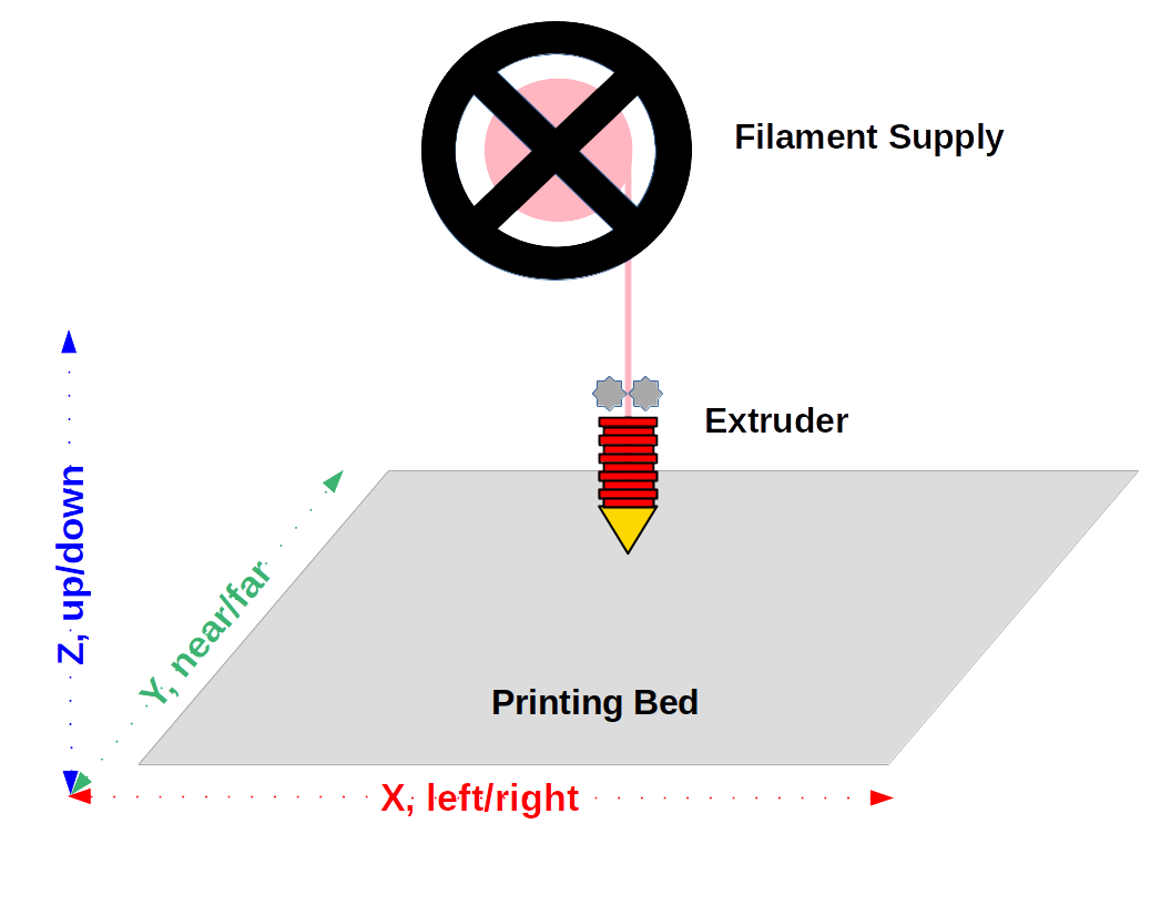
Figure 2: 3D printer basic layout
To print a solid object, the printer must be able to move the extruder in the three dimensions shown in Figure 2. In some printers, the extruder moves up and down (in the Z axis) and the bed moves in the X and Y axes, other printers reverse this scheme and move the bed in the Z axis and the extruder in the X and Y axes. Each arrangement has advantages and drawbacks.
The Perfect Extruder
No single element in a printer's design is as critical as its extruder. The best extruders limit the distance along which the plastic is molten — they try to heat the filament as quickly as possible and over the shortest practical distance. This reduces the chance for a clog or other failure mode in which the filament is neither cold enough for the extruder's gears to push it forward, nor hot enough to flow through the nozzle. Extruders that don't meet these requirements may need to be periodically disassembled and unclogged. Here is a detailed "perfect extruder" diagram:
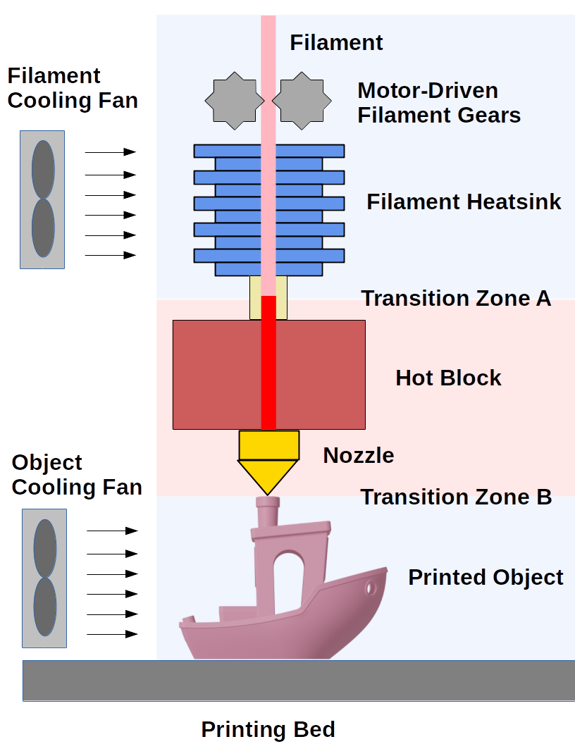
Figure 3: Perfect extruder detail
Notes for Figure 3:
- An extruder includes a motor and gears to propel the filament from its source into the hot block and nozzle. Near the gears the filament must be solid, otherwise it can't be pushed forward.
- In some printers the filament driving motor and gears are located separately — this is called a "Bowden" scheme. The scheme shown in Figure 3 is called a "direct drive". Each of these configurations has advantages and drawbacks.
- Below the driving gears, the filament cooling fan and heatsink keep the filament cool and solid as it approaches Transition Zone A. Without this heatsink, the filament might soften too soon and, instead of moving forward, would melt and foul the driving gears, which would disable the extruder.
- Transition Zone A is a short gap between the filament heatsink and the hot block. In well-designed extruders this zone is very short and the temperature change is very quick.
- The hot block is electrically heated to a temperature above the filament's melting point. When the filament enters the hot block it abruptly liquefies and is propelled toward the nozzle like water through a pipe.
- On entering the nozzle the liquid filament stream is compressed to a smaller diameter, often by a diameter ratio of four or more (cross-sectional area ratio of 16), and its forward velocity increases proportionally.
- In Transition Zone B the plastic exits the nozzle, is deposited on the object and cooled. This cooling solidifies the plastic, so subsequent layers will have a solid foundation.
Problems with Transition Zone B object cooling are easily seen in real-world print examples:
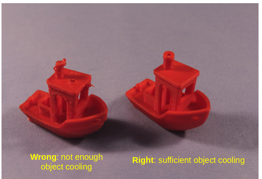
Figure 4: Object Cooling Comparison
In summary, the perfect extruder carefully controls the filament's temperature and allows the filament to become liquid for only a brief time in the hot block and nozzle. This allows the filament propelling gears to work as intended, and it allows new object layers to be deposited on a firm foundation.
The Water Issue
Most filaments absorb water in storage, and unless dried before use, the absorbed moisture can ruin a print or make the part too weak to use. Some filaments are more prone to absorbing water — particularly troublesome in my experience are nylon and TPU (a popular, flexible printer filament).
Because it's particularly sensitive to moisture I chose nylon for this example. In this image are two printed objects:
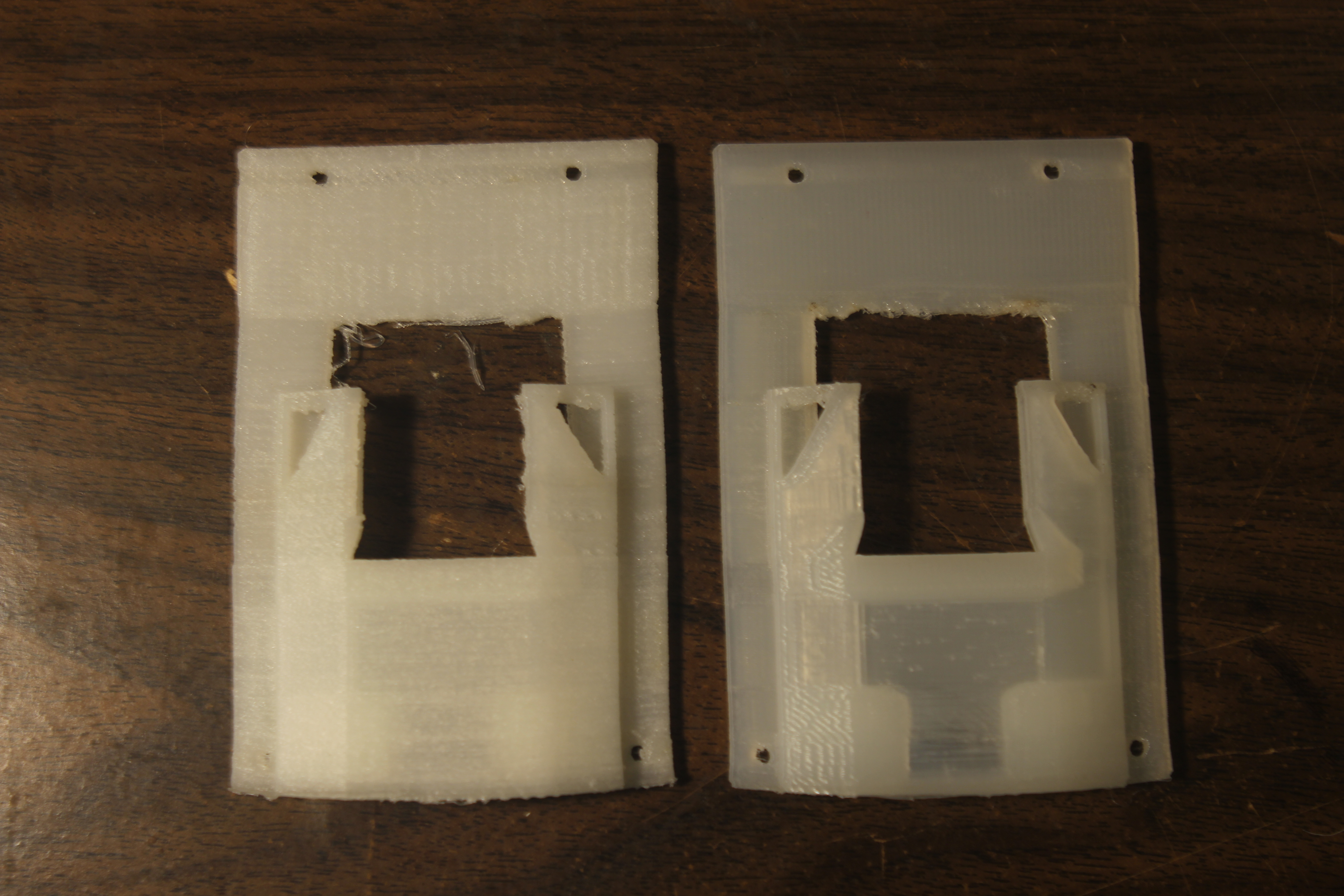
Figure 5: Printed nylon part without (left) and with (right) prior filament drying
At first glance, Figure 5 might seem to be a mere aesthetic comparison — the part on the right looks a little better. But there's more to it — here are microscope images of the same two parts:
Notes on Figure 6: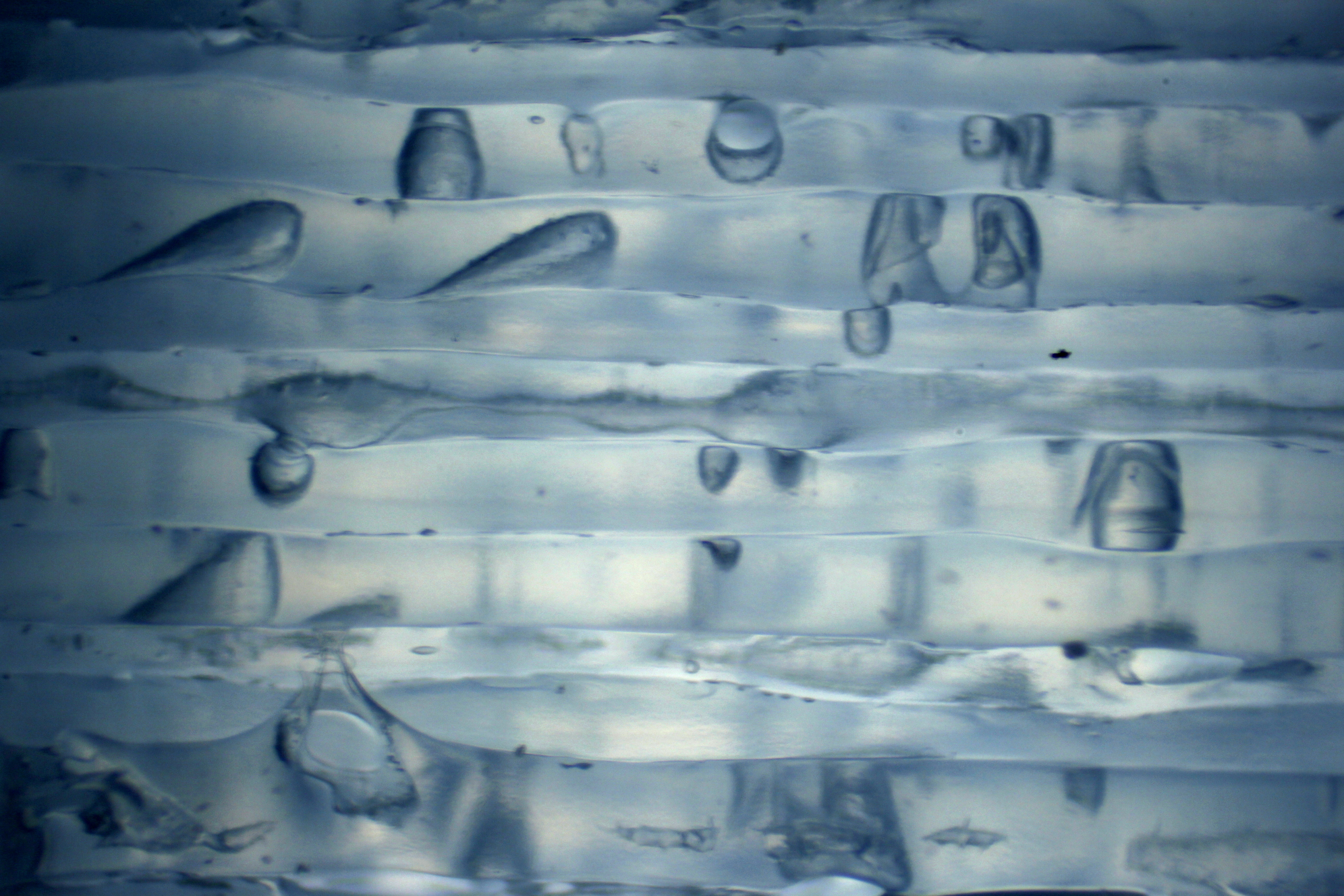
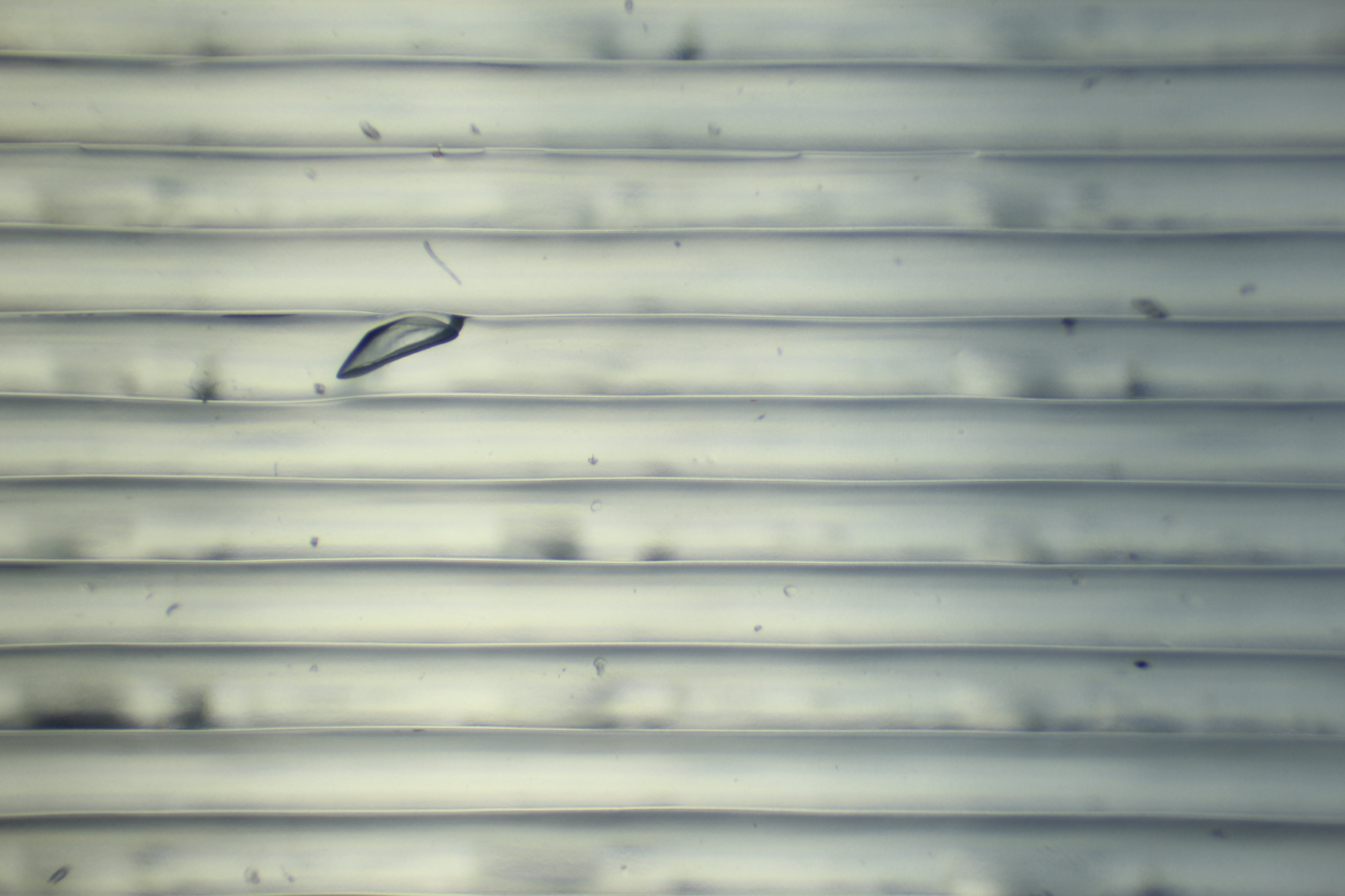
Figure 6: Microscope images (40X): same nylon part without (left) and with (right) prior filament drying
- In the microscope images, the horizontal lines represent the printer's parallel 0.2mm filament paths.
- In the right image, the filament paths are properly fused together and there are few voids.
- In the left image, there are many voids and the paths are jagged and poorly fused.
- The voids are caused by water boiling into steam and leaving fractures and gas pockets behind, places where plastic should be.
- Because of the many voids and the lack of path alignment and fusion, the left part is much weaker than the right (I saw a number of unexpected part failures before learning about the water issue).
As I prepared these microscope images I deliberately found and included a void in the (right-hand) dried-filament example to make a point — one can only reduce the effect of water in filaments, one cannot eliminate it entirely. I dried this filament for 12 hours at 60°C (140°F), but during the two-hour print the filament was exposed to room air and absorbed more water.
Remedies
All 3D printing filaments have the water-absorption problem to some extent. Here are two ways to mitigate it:
Store your filaments in airtight containers along with silica gel (which absorbs moisture):
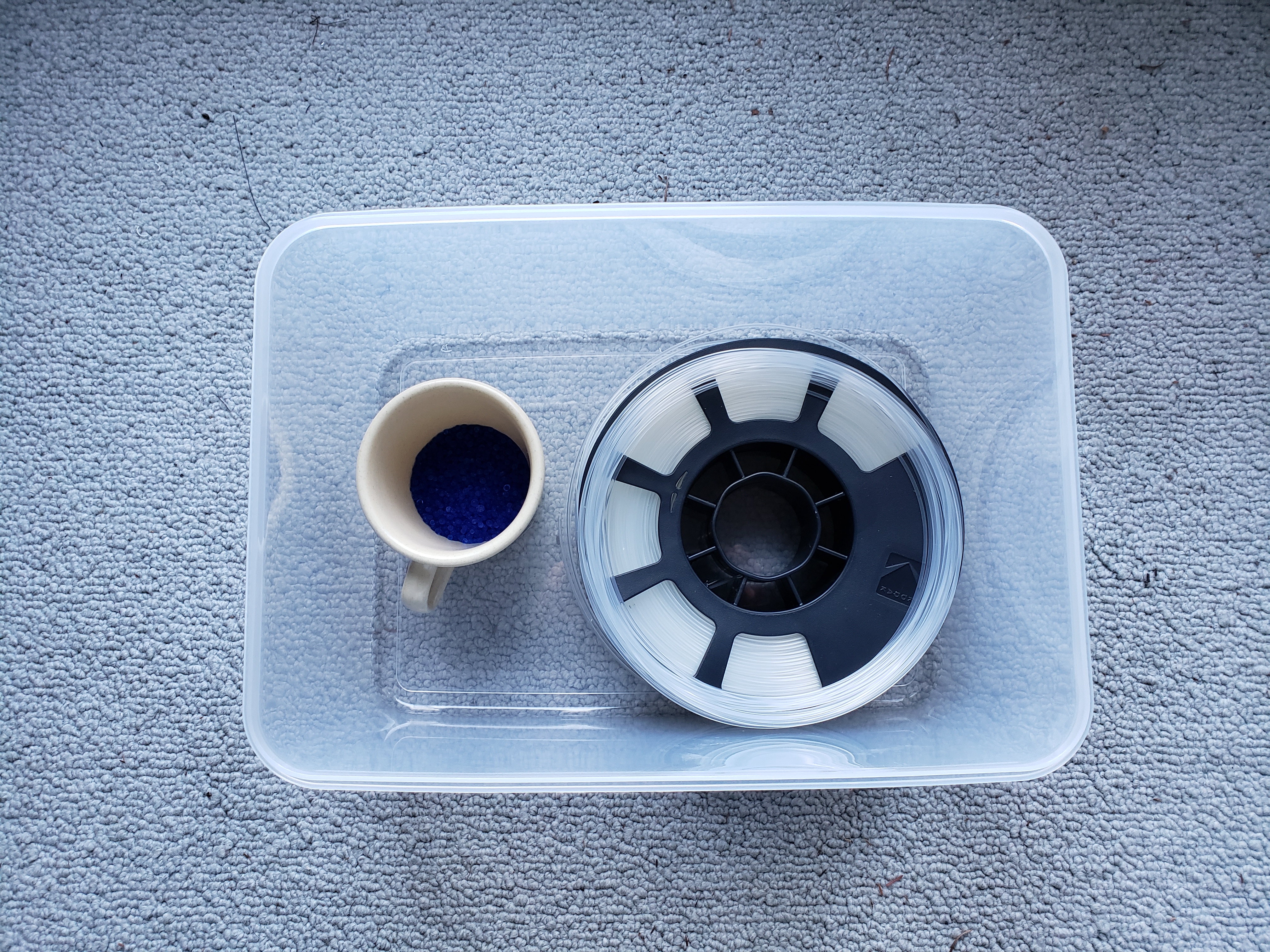
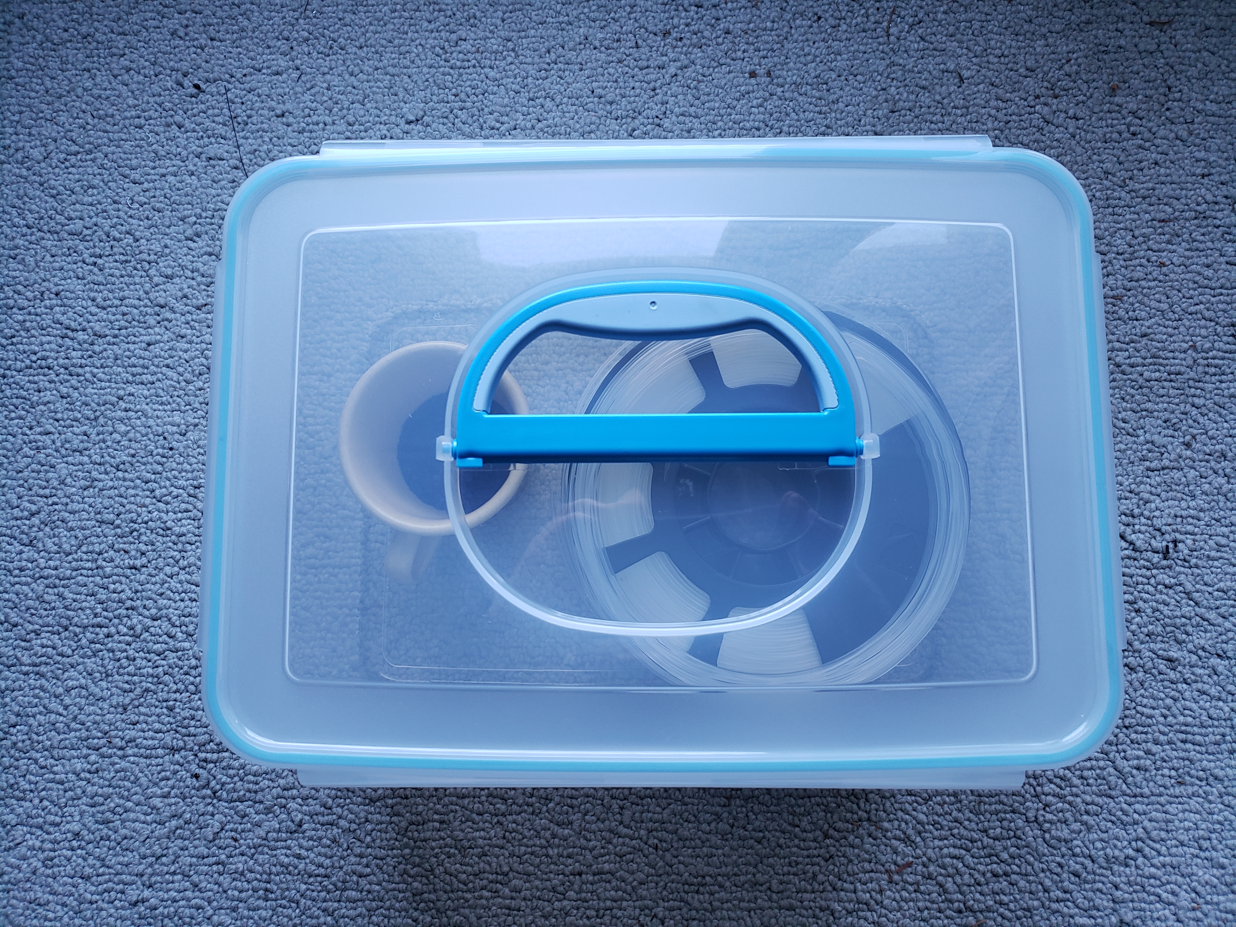
Figure 7: Dehydrating filament storage: airtight box and silica gel (blue beads in cup)
Acquire a food dehydrator and modify it (i.e. create a large internal volume) for use as a filament dehydrator:
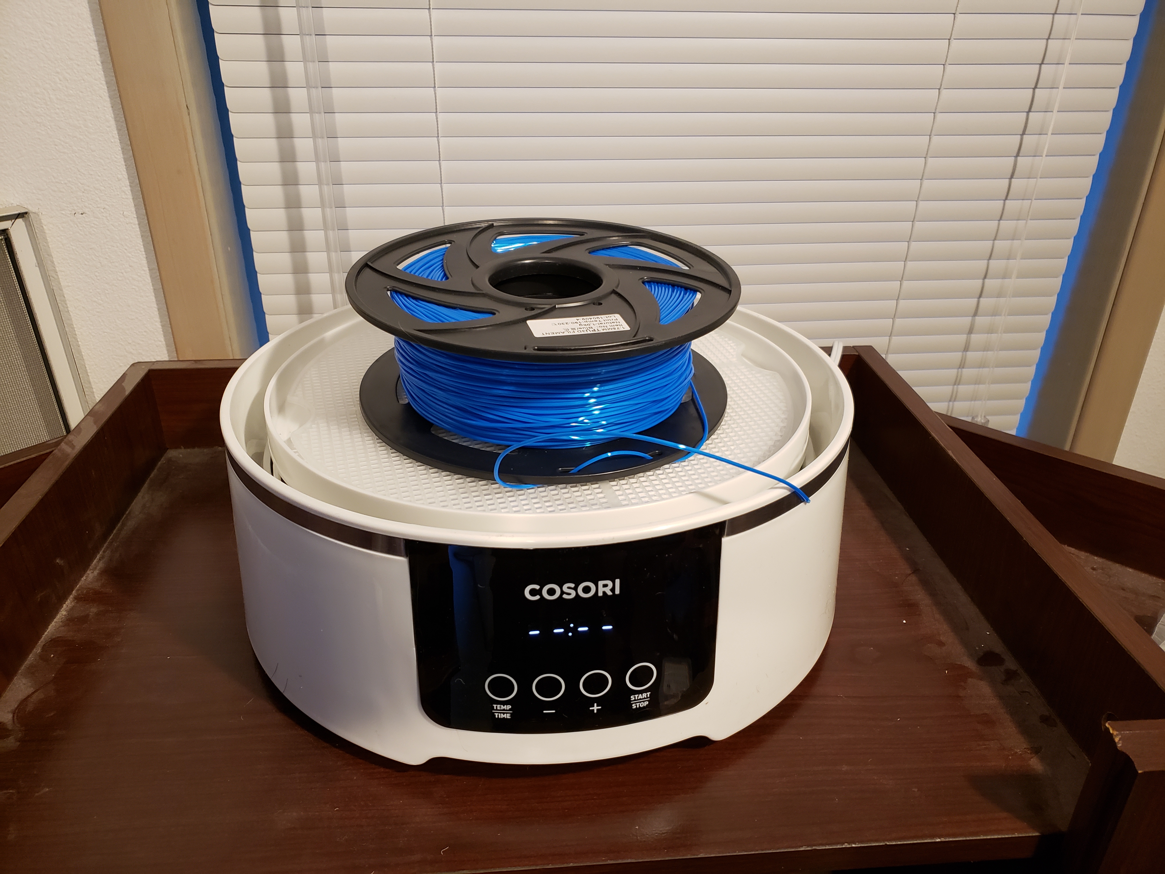
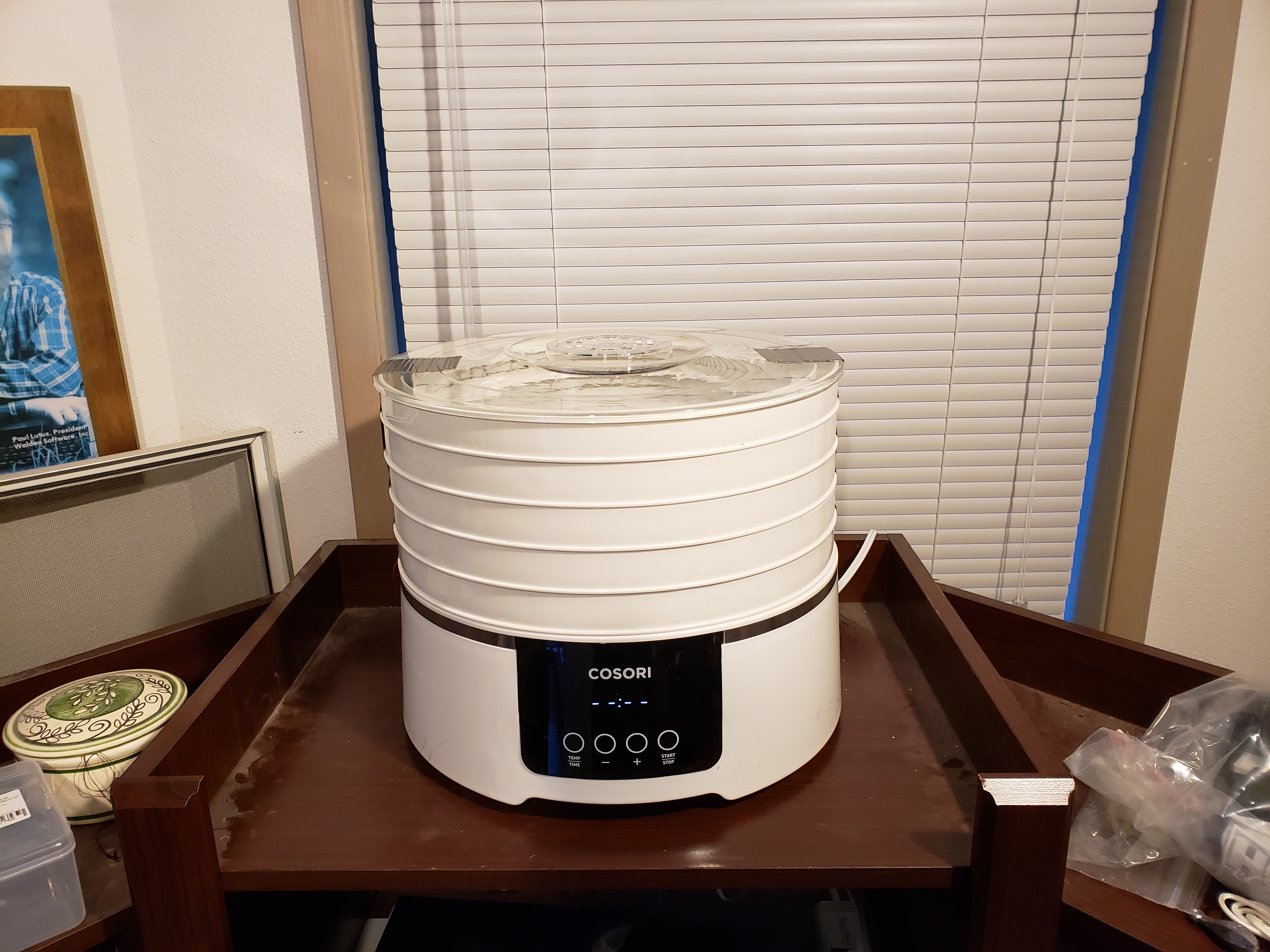
Figure 8: Dehydrating filament appliance (repurposed food dehydrator)
The airtight silica-gel storage shown in Figure 7 can prevent filaments from absorbing environmental moisture, but can't easily dry out a filament that has already absorbed significant moisture. For that, several hours in a food dehydrator or oven is needed prior to (a) performing a print whose outcome you care about or (b) storage in an airtight container. A kitchen oven can be used, but be careful — many cooking ovens don't have accurate temperature settings in the required range, also when large ovens start cold, they may greatly exceed the user's desired temperature before settling down, and this temperature excursion may melt the filament or its storage reel (or both).
Everything that follows is based on personal experience and is just my opinion.
About four months ago I acquired a Qidi Tech X-Max 3D printer, fully enclosed (one of my requirements) with a build volume of X=300, Y=250, Z=300 mm. The printer is advertised as having network connectivity and the ability to print a wide range of materials including those requiring high temperatures. The unit is provided with two extruders, one of which is described as suitable for high-temperature materials.
On setting up this printer I immediately tried to configure a network connection. I quickly realized that neither the wired nor wireless connection was consistent or reliable. After some reconfiguration and physical rearrangement I managed to get a connection to my local network, but although I could ping the machine, it had no open ports and no connection was possible. In online research I discovered others had had this same problem, but even with replacement motherboards (Qidi Tech has very good customer service), the issue remained unsolved.
Oh well, I said, not very important — I can always plug in a USB device to move G-code files to the printer.
I quickly encountered issues with extruder fouling, and after a few extruder disassemblies and repairs I could see why — the filament cooling fan and associated hardware didn't create the essential rapid heat break (shown as Transition Zone A in Figure 3 above) that leads to reliable extruder performance. This means if the hot block temperature was set a bit too high, the filament would soften too soon and foul the driving gears, if too low, the filament would seize up in the hot block. On average, the outcome was a little bit of both.
After a few extruder disassemblies and repairs, each of which required removing the extruder from the printer, the tiny ribbon cable connector's release handles broke off, which resulted in the connector jamming onto the extruder and requiring very careful and delicate removal methods to minimize further damage. More online reading revealed others had experienced this same problem.
Oh, well, I said, I'll replace the cable with something more robust and suitable for a machine that requires regular maintenance.
Then, interested in stronger, more durable parts, I tried printing using ABS filament. This meant using the second, "high-temperature" extruder. I quickly realized the second extruder was only slighty different than the default unit and had the same issues — no clean heat break, poor design, no part cooling fan* (required for ABS), and the presence of an internal PTFE tube where metal was needed, plus Qidi Tech's statement that this particular extruder couldn't be repaired, only replaced.
At this stage I realized what I had done — I had bought a printer without enough information or experience to make an informed choice, and worse, I hadn't located and read the many online conversations about this specific printer and its problems.
It was decision time. I wanted a printer like the Qidi Tech X-Max — fully enclosed, large print volume — but with better electronics, a better extruder, and above all, a more reliable cable to connect the motherboard to the extruder. Few available printers met all my requirements, and the Qidi Tech printer was already present — it only needed to be completely rebuilt. Also, I'm not the kind of person who returns things, especially when the purchase results from my own bad decision-making.
I laid out a plan to upgrade everything except the enclosure, the mechanical parts and the heated bed — I intended to replace all the electronics, the extruder, and the cabling. I have the right background for this kind of project, so I was confident I would succeed.
Before I start this section, I want to say that Qidi Tech has terrific customer service. I may have issues with their printer and its design, but they're doing an excellent job reaching out to their customers.
Also, there are many links in this section to Web sites having needed parts. I apologize in advance for links that are certain to become invalid over time.
Here's a quick summary of the rebuild (details follow):
- I replaced the original motherboard (the one lacking network connectivity) with a Duet2Wifi, which is a DIY-oriented motherboard often used to upgrade existing equipment.
- I found that the Duet2Wifi motherboard has three separate network paths to communicate with the printer — HTTP, FTP and Telnet, all of which work. It has an HTTP server and a sophisticated control Web page.
- I replaced the original extruder mechanical assembly with a BMG extruder mated to an E3D V6 all-metal hotend in an optimal direct drive configuration as shown in Figure 3 above.
- If you order a BMG extruder assembly as shown above, avoid getting the wrong "handedness". The extruder linked above is the right choice (in both the logical and handedness sense), but there's another almost-identical extruder, but reversed left-to-right, for dual extruder setups. The extruder mount project described next needs the "right" part, not the "left" one.
- I located and 3D printed this Thingiverse project for the extruder mounting (it seems many people have replaced Qidi Tech's extruders).
- I replaced the Qidi Tech cable with a ribbon cable scheme that uses press-fit connectors, so any future cable failures are easily fixed (more details below).
Bootstrapping
In one of the most fun parts of this project, I used the old Qidi Tech motherboard, extruder and ribbon cable to 3D print the Thingiverse project parts to be able to mount the new extruder on the Qidi Tech mechanical rails. Engineers call this "bootstrapping," which (among other things) means relying on existing equipment to create new equipment. It was a classic Catch-22: I couldn't use the new, much better extruder until it had a reliable mounting, and the new mounting needed to be 3D printed using the old Qidi Tech extruder (which for reliable ABS printing involved a lot of repairs and tuning).
Here are some pictures:

Figure 9: The most chaotic moment in the project (click for full-size).
The Duet2Wifi control Web page is on display in the background.
Figure 10: The new Duet2Wifi motherboard and associated wiring (click for full-size).
Note the ribbon cable with press-fit connectors at bottom center.
Figure 11: The new extruder mounted and in service (click for full-size).
Notice another pair of press-fit connectors on the extruder mount.
Figure 12: The cable handler I (click for full-size).
This scheme keeps the cable from falling onto the heated bed, where it will surely be torn to pieces.
Figure 13: The cable handler II (click for full-size).

Figure 14: The Y-stop adjuster, details and source below (click for full-size).
Some details
- The ribbon cable is a common 14- or 16-conductor cable like this. I chose 14 conductors to keep the weight down, but it probably doesn't make much difference. In any case, get 16-conductor connectors, which apart from being easier to find, can be used with either 14- or 16-conductor cable. That way you can expand in the future.
- The 16-conductor press-fit connectors are:
- The advantage of the ribbon cable and press-fit connectors is that you can change configurations or make repairs very easily, especially if you have installed a connector pair near the motherboard (Figure 10) as well as at the extruder (Figure 11).
- If you want to support a bed leveling sensor you will need more than 16 conductors, but this is feasible once you have a cable handler in place (Figures 12 and 13 above). (I still level my print bed the old-fashioned way.)
- I added the cable handler after watching the heated bed descend, snag my new ribbon cable, and shear right through it. As shown in Figures 12 and 13, the handler is just a piece of lightweight flexible nylon cord (about 2mm) and a 1.5 ounce (≅ 43 gram) lead weight. Drill one new hole at the location shown in Figures 12 and 13.
- The advantage of the lead weight over a rubber band or shock cord is that the restraining force is constant at all cable positions.
- I created the Y-stop adjuster shown in Figure 14 because the original Thingiverse project was meant for a slightly different Qidi Tech printer model and I saw an interference issue (that's a "collision") in which the new extruder's part cooling fan crashed into the printer's internals before the Y microswitch could be tripped. Here is an STL file for the adjuster, and my original FreeCAD design file in case more adjustment is needed.
- On the topic of axis alignment and travel, before choosing maximum travel numbers for the new extruder, and before starting serious printing, make sure the X axis bars are at exact right angles to the Y axis and to the printer as a whole (this also affects the outcome when printing rectangular parts, which won't be rectangular if this adjustment isn't made). To adjust the X axis, simply apply some rotational force to the X axis bars while looking at an alignment reference, like part of the enclosure or a target placed on the heated bed. The X axis can easily get out of adjustment because alignment of the X axis depends on the synchronized motion of two belts, one at the left, one at the right.
- As shown in Figure 11, I added a large, stiff cable tie around the middle of the extruder mount, rigidly tying the carriage part to the top frame part — when printed in ABS the original design was too flexible for my taste. Put one on each side.
- In the original Thingiverse project there is a belt clip that fixes the carriage to the belt, with various available sizes. If possible, print this in nylon, because if printed in ABS or another material it tends to deform over time and eventually loses its grip on the belt.
- In fact, while we're on the topic, if practical all the extruder mount parts should be printed in nylon — better strength and durability, more resistance to warping at high temperatures.
- Be sure to acquire a brushless fan like this for the E3D V6 all-metal hotend. The linked hotend kit comes with a brush-type motor, which you don't want to use for these reasons:
- The Duet2Wifi literature warns against using brushed fan motors on the PWM (Pulse-Width Modulation) driver circuits — motherboard damage may result.
- When driven using PWM at anything but 100% duty cycle, a brushed motor just stops running. Only a brushless motor responds correctly to this kind of speed control. If the filament cooling fan should ever stop running while the hot block is powered (see Figure 3), the extruder will need to be rebuilt.
- It's the same issue for the part cooling fan — make sure to acquire a brushless-motor fan like this.
- When setting up the Duet2Wifi board and new extruder, connect the part cooling fan to the board "Fan 0" PWM output, the extruder cooling fan to the "Fan 1" output, and the Qidi Tech enclosure ventilation fans to the "Fan 2" output. This scheme is more or less mandated by the way the Duet2Wifi board works.
- Click here for a browseable directory of my G-code files for this project. The file config.g in particular should provide a good starting point for your configuration of a Qidi Tech X-Max or other similar printer.
- Click here for a browseable directory of this project's macro files. Among other things the macros manage the activities that were originally handled by the Qidi Tech control panel.
New Ribbon Cable Pin/Color/Assignment Table
These are just suggestions based on my project experience.
Pin # Color Assignment Motor Cable Type 1 Color Motor Cable Type 2 Color 1 Brown Extruder Stepper Black Green 2 Red Extruder Stepper Red Red 3 Orange Extruder Stepper Green Blue 4 Yellow Extruder Stepper Blue Yellow 5 Green Hotend heater A (parallel 5 & 6) 6 Blue Hotend heater A (parallel 5 & 6) 7 Violet Hotend heater B (parallel 7 & 8) 8 Gray Hotend heater B (parallel 7 & 8) 9 White Thermocouple/Thermistor 10 Black Thermocouple/Thermistor 11 Brown Extruder cooling fan - 12 Red Extruder cooling fan + 13 Orange Part cooling fan - 14 Yellow Part cooling fan + I added the "motor cable" columns because there were some short motor cables with connectors left over from the original Qidi Tech wiring and I decided to use them — but each had different colors.
To use a thermocouple with the Duet2Wifi motherboard, a thermocouple daughterboard is needed, readily available. A thermistor sensor is (a) easier to connect and use and (b) usable up to 350°C. Polarity matters only with a thermocouple, not with a thermistor.
After this conversion the build volume is slightly smaller (X=0:299, Y=0:240, Z=0:294, all mm), mostly due to the larger size of the extruder, which affects both the Y and Z axes.
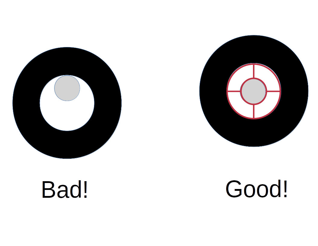
Figure 15: The filament reel adaptor problem.
There are a number of problems with how printer manufacturers handle filament reels. One is that a filament reel should fit snugly and be balanced around its supporting shaft, to minimize the force required to draw the filament from the reel into the printer. So I wrote a Python program that creates 3D printable user-defined reel adaptors that control for various vendors' reel axle sizes and widths, as well as the diameter of the support axle. Then I wrote another Python program that (working with Blender) generates a complete set of adaptor STL files based on a user-generated set of specifications.
Here are the Python programs:
- create_adaptor.py — the adaptor generator.
- create_adaptor_set.py — a user-configurable program that creates a set of STL files for adaptors based on different manufacturers' reel dimensions.
Here's how to use these programs:
- Be running Linux (if not, you're on your own ... sorry).
- Install Blender, most recent version (2.8 at the time of writing).
- Download both create_adaptor.py and create_adaptor_set.py from the links above. Make the files executable.
- Edit create_adaptor_set.py, add your desired adaptor specifications and edit the final line in the file to specify where you want the adaptor STL files to be saved.
- Run create_adaptor_set.py like this:
$ blender -P create_adaptor_set.py- If things have been set up correctly, all your specified reel adaptor STL files will be generated, ready for printing.
I can't tell you how many YouTube videos I've watched in which people hung filament reels on support shafts that weren't remotely the right size to support the reel, apparently without realizing how much extra force is required to draw filament from an unbalanced, uncentered reel (unless the reel's content happens to be perfectly balanced ... which never happens). This project solves the problem.
This addresses a Qidi Tech specific problem — the factory-provided filament reel retainers (the two plastic devices that hold the filament reel onto the shaft) aren't designed very well. When they're first used, they're extremely tight, but after a few months they're too loose to do their job. The reason is there's no flexibility built into their design — the retainers have their internal diameter pressed directly onto the shaft. It's initially too tight, then after some plastic has been scraped away through use, it become too loose. This project solves the issue with a better design.
Here's how my retainer looks (according to Blender):
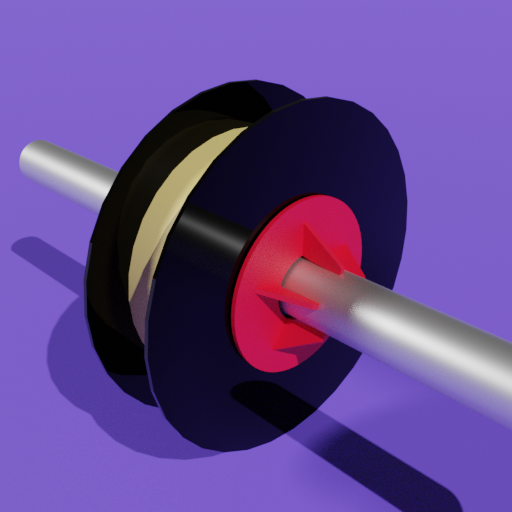
Figure 16: Filament Reel Retainer.
This retainer uses the natural flexibility of ABS and a system of gripping fingers to maintain a consistent grip force over long periods of time. If more force were desired, a user could edit the FreeCAD design file to increase the thickness of the base disk and re-print. Here are some links:
- My original FreeCAD design file so readers can make changes.
- An STL file for printing an adaptor suitable for the Qidi Tech X-Max shaft size.
This section is about the connection between mathematics and everyday reality. Unlike the earlier sections there are no repairs, practical tools, or remedies for printer defects — just an intellectual adventure. The results are interesting and can be 3D printed.
Greek philosopher Plato is remembered for having described a realm of pure thought, a concept he called the Theory of Forms. Plato regarded this realm, a realm of pure thought and ideas, as more real and more basic than everyday reality.
While addressing the Problem of Universals, the philosophical question of what basic ideas and principles lie beneath everyday reality, Plato described what we now call the Platonic Solids, a set of geometric constructions meant to represent the realm of pure thought. In this project, I generate 3D-printable framework representations (meaning vertices and edges, no enclosing faces) of the Platonic Solids:
Name Faces 2D Image 3D Image
Tetrahedron 4 

Cube 6 

Octahedron 8 

Dodecahedron 12 

Icosahedron 20 

Just for fun I added some extras to the classic Platonic Solids collection:
Name Faces 2D Image Hypercube 20 

Buckyball 32 

As with the earlier programs, the Platonic Solids generator is a set of Python programs that rely on Blender to show the results and export STL files for 3D printing (all the above graphics were generated in Blender). Here are the programs:
- generate_platonic_solids.py, the math-based generator for all the solids.
- generate_all_platonic_solids.py, a convenience program that generates all the Platonic Solids and the extras (i.e. hypercube and buckyball) and puts the printable STL files in a directory named "results".
NOTE: While developing this Web page I noticed that when the above Python programs are displayed in a browser, some Unicode characters aren't being rendered correctly. Annoying, but not a serious problem — just download the programs, where the Unicode characters will be correctly displayed in your programming editor.
Here's how to use these programs:
- As before, be running Linux (if not, you're on your own ... sorry).
- Install Blender and get the most recent version (2.8 at the time of writing).
- Download both generate_platonic_solids.py and generate_all_platonic_solids.py from the links above. Make the files executable.
- Create a subdirectory "results" in the directory where the programs are located.
- Run generate_all_platonic_solids.py like this:
$ blender -P generate_all_platonic_solids.py- If things have been set up correctly, a complete set of printable STL files of the Platonic Solids — plus the extra objects Hypercube and Buckyball — will be generated and saved in the "results" subdirectory.
- If the resulting STL object files don't create the desired object sizes or have edge members that are too thick or thin, change the controllling constants in the generate_all_platonic_solids.py program and run it again.
Some of the Platonic Solids STL files are very difficult to print, because of severe overhangs and long almost-horizontal bridging areas. In my experience the Buckyball is the most difficult, because of its complexity and all the angles it contains. This object set is a real test of one's 3D printing skills, but don't feel bad if things don't turn out perfectly — given the current state of 3D printing technology, some things aren't meant to be printed.
There are few fully enclosed large-volume printers able to print high-temperature materials, and none for modest prices, so even though I had to rebuild this printer, I got a good result for a reasonable price. Now I have to figure out how to print large nylon parts that don't warp and/or break free from the print bed during printing (a common problem with nylon, not easily solved). Once I solve this issue I'm planning to reprint the new extruder mount in nylon for more robustness and resistance to high temperatures.
A DIY purist, one with more 3D printer experience, would have bought a pile of parts and built a printer from the ground up, and that's what I'll do the next time I start a printer project. If carefully planned, such a project would have fewer compromises. But this was a reasonable first-printer project.
The Duet2Wifi motherboard's control Web page is pretty complete. It has temperature graphs and many kinds of controls available to monitor and control the printing process. Printer manufacturers that include dedicated control panels at extra cost must think their customers don't have cell phones (maybe they're right). As I see it, the lowest-cost 3D printer of a given kind should rely on the customer having access to a Web browser rather than adding an expensive, failure-prone touch-sensitive control panel. But for that to be the norm, the printer's electronics would need to create a reliable network connection, which wasn't true for this printer's original motherboard.
The Metric System
There's a hidden advantage to 3D printing projects — you have to think in metric. All the sizes and temperatures are metric by default, even in U.S.-designed equipment. I've always been a fan of the metric system, so for me it was an added advantage, but for many Americans, metric immersion is a new thing.
Can you tell that I think the U.S. should convert to metric? Only three countries still use the old imperial system — the U.S., Liberia and Myanmar — and the latter two intend to change over to metric.
It's not as bad as it might sound, because there's a progressive "bottom-up" metric conversion going on, as one U.S. industry after another converts to metric just to keep its customers. By "bottom-up" I mean individual companies and agencies (NASA, the entire pharmaceutical industry, Ford Motor Company, John Deere, Caterpillar, Xerox and others) have independently converted to metric rather than having a metric conversion mandate descend from the federal government (that would be "top-down"). Bottom-up change is the norm in a country where the alleged leaders are actually followers.
Thanks for visiting and reading!
| Home | | 3D Printing | | | Share This Page |